Most relief systems are sized for scenarios that behave themselves. Fire, blocked outlet, thermal expansion, control valve failure. The fluid stays essentially single phase, the methods in API 520 Part I apply cleanly, and the answer holds up under review. Then a reactive scenario arrives, the same methods get applied out of habit, and they return an area that is comfortably, confidently, dangerously small.
This piece sets out what actually governs the sizing, the equations we use, what each one assumes, and where the input data has to come from. It is written for engineers who have to produce or check a number rather than for readers who want the idea.
Why a runaway is a different problem
In a runaway the device is not passing vapour off a quiescent boiling liquid. The contents are self heating, the reaction rate is still accelerating while the vessel vents, decomposition may be generating permanent gas, and the swelling two phase mixture can carry liquid out through the nozzle. Two consequences follow and both work against you.
The first is that mass flow does far less work than you expect. A kilogram of vapour removes the latent heat of vaporisation. A kilogram of entrained liquid removes almost nothing. Vent a two phase mixture and you are discharging a great deal of material while cooling very little, so the required area rises sharply relative to the vapour only case.
The second is that pressure keeps climbing after the device lifts. The peak pressure in a reactive scenario is not the set pressure. It is wherever the still accelerating heat release and the relief capacity finally balance. Sizing to the set point rather than to the accumulated pressure you can actually tolerate is not a conservatism error, it is a structural one.
What it looks like when the relief cannot cope
On 19 December 2007 a reactor at T2 Laboratories in Jacksonville, Florida ran away during the production of the gasoline additive MCMT. Cooling was lost, the reaction accelerated, and the relief system could not remove energy fast enough to stop the vessel bursting. Four people were killed and thirty two were injured, several of them offsite. The US Chemical Safety Board investigated and found that the company had not recognised the reactive hazard of the process it was running.
This video is hosted by YouTube and loads only after you accept cookies.
The engineering lesson is narrow and worth stating plainly. A relief device had been fitted. It was not adequate for the scenario that arrived, because the scenario that arrived was a runaway reaction rather than the cases the device had been sized against. Everything that follows in this article exists to stop that particular gap opening.
Classify the system before you size anything
The DIERS work separates reactive venting into three behaviours, and the required area differs sharply between them. Getting the classification wrong produces a confidently calculated answer to the wrong question, and it is not conservative in either direction.
- Vapour or tempered. Latent heat of vaporisation removes energy and holds the temperature at the boiling point corresponding to the relief pressure. Venting tempers the reaction, so the system can be brought to a stable state.
- Gassy. Permanent non condensable gas is generated by decomposition. There is no tempering mechanism at all, temperature continues to rise regardless of venting, and sizing is governed by the peak gas generation rate.
- Hybrid. Both mechanisms present together. The most demanding to characterise and, in our experience, the most commonly misclassified.
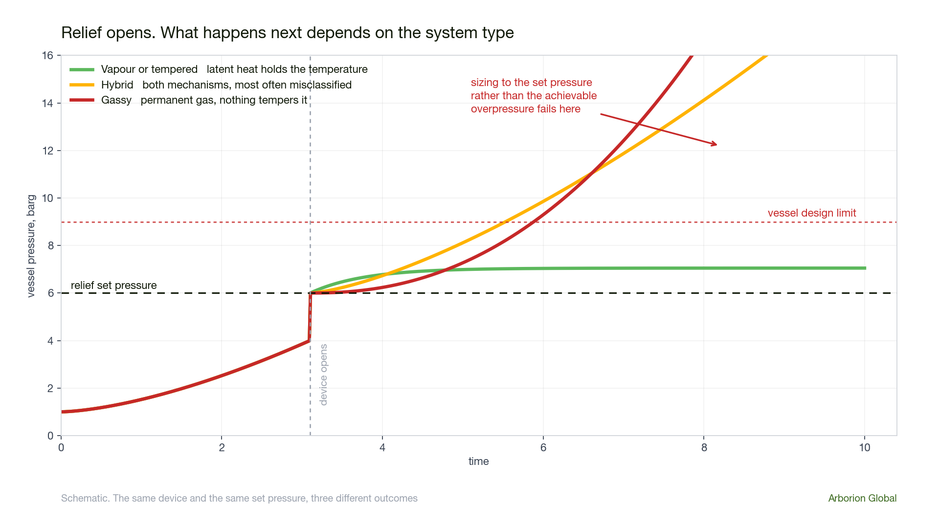
A gassy system sized as though it were tempered can be out by a margin that no conventional safety factor will rescue. Classification comes from the test data, specifically whether the pressure returns as the sample cools, not from an assumption about the chemistry.
Correcting the calorimetry before it reaches the sizing
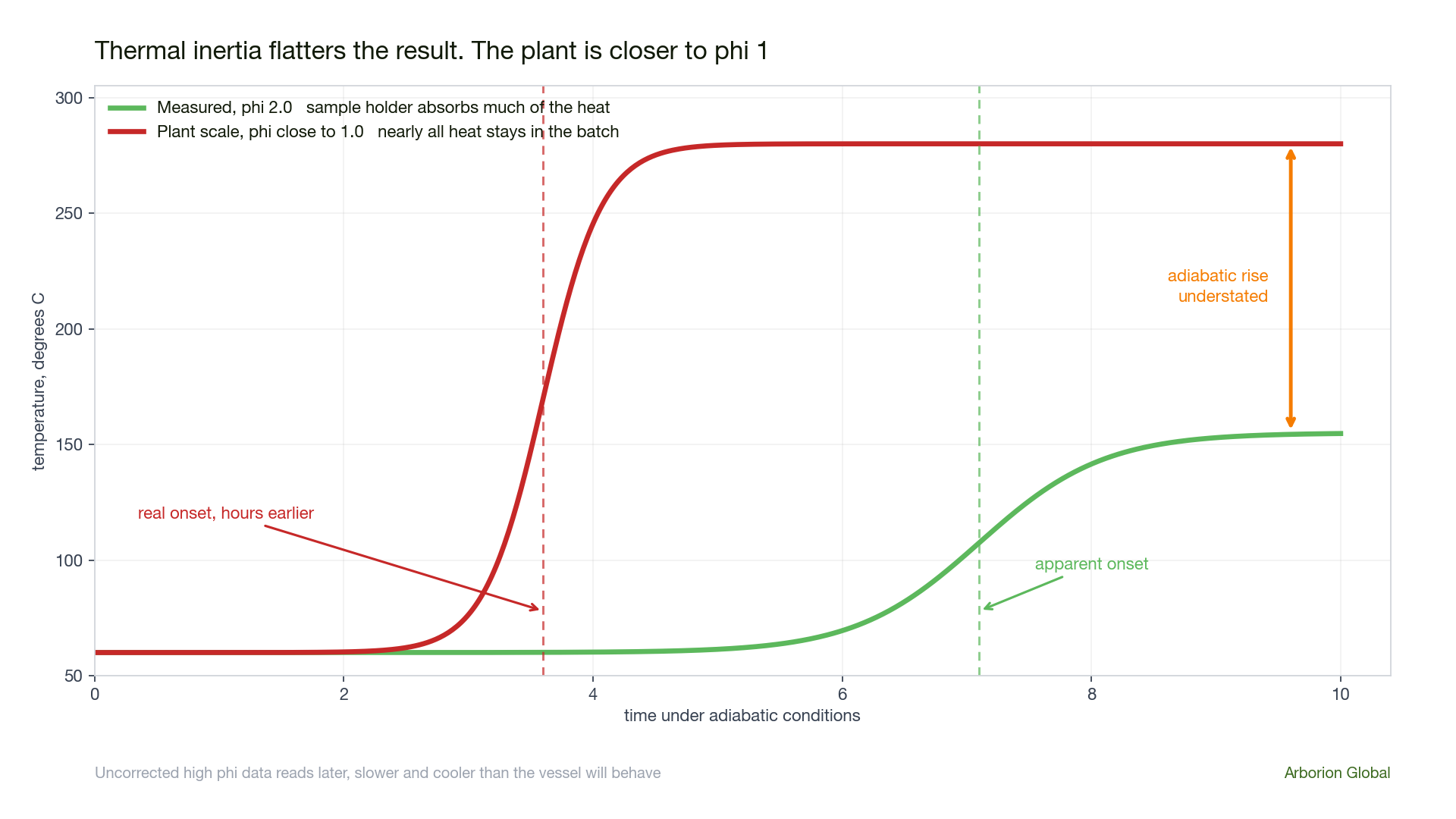
Every number that feeds the vent sizing comes from a calorimeter, and every calorimeter absorbs some of the reaction heat into its own hardware. The phi factor, or thermal inertia factor, quantifies that.
- thermal inertia factor, dimensionless
- mass of the sample container, kg
- specific heat of the container, J/kg·K
- mass of the sample, kg
- specific heat of the sample, J/kg·K
Both the adiabatic temperature rise and the self heat rate must be corrected before use. The corrections move in the direction that matters, which is why uncorrected data always flatters the design.
- adiabatic temperature rise, K
- self heat rate, K/min
The self heat rate correction above is the common first order treatment and is adequate for most vent sizing. Where the reaction order and heat of reaction are being extracted for kinetic modelling, the full correction depends on the reaction order and should be handled explicitly.
Sizing a tempered system, Leung's method
For a vapour tempered system the widely used closed form is Leung's equation. It assumes homogeneous vessel behaviour, which is to say no vapour disengagement, and it is the starting point for most tempered sizing.
- required relief area, m²
- initial mass of contents, kg
- heat release per unit mass at set pressure, W/kg
- mass flux through the device, kg/m²·s
- vessel volume, m³
- latent heat of vaporisation, J/kg
- specific volume change on vaporisation, m³/kg
- liquid specific heat, J/kg·K
- temperature rise between set and maximum accumulated pressure, K
Leung's equation assumes homogeneous venting with no vapour liquid disengagement, uniform vessel temperature, vapour liquid equilibrium at the vent, and physical properties treated as constant across the relief interval. Where disengagement genuinely occurs the area falls, but claiming it requires evidence from the test data rather than an assumption.
Mass flux and the omega method
The term G above is not a constant you can look up. Two phase flashing flow through a nozzle is compressible and usually chokes, and the mass flux depends on how much the mixture flashes as it depressurises. Leung's omega method reduces that behaviour to a single compressibility parameter.
- compressibility parameter, dimensionless
- inlet vapour mass fraction
- inlet specific volume, m³/kg
- inlet vapour specific volume, m³/kg
- inlet temperature, K
- inlet pressure, Pa
- liquid specific heat, J/kg·K
The critical pressure ratio is then found by iteration, and the choked mass flux follows from it. For flow that does not choke, the exit pressure replaces the critical ratio in the same framework.
- critical pressure ratio, solved iteratively
- mass flux at choked conditions, kg/m²·s
Inlet line pressure loss deserves the same scrutiny as the device. The conventional limit is three percent of set pressure, above which the valve can chatter and lose capacity. On reactive duty, where the device may pass two phase flow at high mass rate, that limit is easy to breach with a nozzle and short run that looked adequate on the drawing.
Sizing a gassy system
A gassy system has no tempering mechanism, so there is no equilibrium temperature to size against. The vent has to pass the peak volumetric gas generation rate at the accumulated pressure you are willing to reach. The governing input is therefore the maximum gas generation rate measured in a closed test and corrected for phi, not a heat release rate.
Because the temperature keeps climbing whatever the vent does, gassy sizing is far more sensitive to the allowable overpressure than tempered sizing is. Small changes in the pressure you are prepared to accept move the required area substantially, which is why the vessel MAWP and the relief set pressure should be settled before the calculation rather than after it.
A worked tempered case
The numbers below are illustrative but realistic for a jacketed reactor on a specialty chemical plant. They show the shape of the calculation and the order of the answer.
- Vessel volume V = 5 m³, contents m₀ = 4000 kg
- Set pressure 4 barg, maximum accumulated pressure 5.2 barg
- Heat release at set pressure q = 25 W/kg, phi corrected
- Latent heat h_fg = 350000 J/kg, v_fg = 0.28 m³/kg
- Liquid specific heat Cv = 2100 J/kg·K, ΔT = 18 K
- Mass flux G = 3200 kg/m²·s from the omega method
The area is only half the answer. Check that the downstream system, the header, the knockout drum and any scrubber or flare, can accept two phase discharge at this rate. A correctly sized device discharging into a system designed for vapour has relocated the problem rather than solved it.
The calculator below runs the same two steps on your own numbers. It applies the phi correction, then Leung's equation, and shows what a vapour only view would have told you for comparison.
Tempered vent sizing calculator
Leung's equation with phi correction. Screening use only.
Where the data has to come from
None of the above can be sourced from a P&ID or a handbook. It requires adiabatic calorimetry with thermal inertia low enough to represent a plant vessel, or properly corrected where it is not.
- VSP2, Vent Sizing Package 2. Low phi around 1.05 to 1.10, closed and open cell, the reference apparatus for vent sizing data.
- ARSST and RSST. Low phi screening, fast and inexpensive, well suited to classification and to ranking scenarios before committing to full testing.
- APTAC. Pressure tracking adiabatic calorimetry across a wide pressure range.
- ARC. Higher thermal inertia, typically phi 1.5 to 3. Useful for onset and TMRad work, but the data must be corrected before it informs a vent area.
DIERS Project Manual, Emergency Relief System Design Using DIERS Technology, AIChE. API STD 520 Part I for sizing and selection and Part II for installation. API STD 521 for pressure relieving and depressuring systems. ASME BPVC Section VIII Division 1, UG 125 to UG 137. ISO 4126 for safety devices against excessive pressure.
Checks for an existing installation
- Was a runaway relief case assessed at all, or only fire and blocked outlet?
- Was the system classified as vapour, gassy or hybrid, and on what test data?
- Was the calorimetry phi corrected, and what was the phi factor?
- Was sizing done at the accumulated pressure actually reachable rather than at the set pressure?
- Was two phase flow considered, and if it was discounted, on what evidence of disengagement?
- Is the inlet line loss within three percent of set pressure at the reactive mass flow rate?
- Can the downstream system accept two phase discharge, or was it sized for vapour?
Relief is the last layer of protection. It is worth knowing whether it is real, and that means knowing which of the questions above your current documentation can actually answer.